2016-02-02

Ottawa Mystery challange 2016 - dog trainier

Ottawa mystery challenge 2016

Dog trainer device

Once again it's a mystery challenge and this time the mystery component is same as before (ir distance sensor) but I'm not allowed to do the same thing (kinetic-lance) so I have to do something new.
My daughter is deep in to dogtraining and wanted me to do some project to allow a dog to communicate by pressing buttons or something.
The first tought was a few "that was easy" buttons from staples but they are quiet hard to press on (with a nose) so some other thing is needed. Was thinking some kind of pad with a switch but then this challenge came up and of course that is the answer, use a distance sensor to see if a paw/nose is above a picture of walking outside and if so play a sound snippet saying "walk", and same for other things like food, play, go outside and so on.
This can be done in multiple levels. Starting with fixed pictures of 3 things to have a monitor showing things and have them change depending on action (can't get treat all the time)/time of day (no food before 5) and so on.
Details to be worked out but the basic part of sensing if a nose/paw is in the sensors path is the common part and that's what we start with.

2015-09-23

Electronic enigma replica


I have always had some interest in cryptology and secret stuff like that. I did read up on how the German Enigma worked before I ended high school so it's not precisely a new idea that I want to make a enigma replica of some kind.
Yes, it does exist several in various degree of complexity already but the interesting part isn't to have one, it's to make one so they don't count (and they all have something I don't like or missing something I want).

My plan is to make an electronic Enigma replica that on the outside looks very much like the original - as far as cost allows.
Inside it will of course be all electronic with LEDs, alphanumeric display for rotors and so on.
I have a ruff plan on how to do it in my head and as of today I have ordered a pile of parts from ebay and aliexpress so in a month or two I should be able to start assembly.
My plan is to have
* one top PCB with the alphanumeric display, the rotors (made of rotary pulse encoders and a 3D printed wheel), switches and an arduino clone.
* next PCB is just the light board with it's 26 LEDs
* next PCB is the keyboard with it's 26 Keys
* last PCB is the front side plug board with sockets and a little of smarts in it
The boards are connected with a flat cable working as a bus
By splitting up the parts design of on part can be changed without impacting the rest. The keys can be simple tactile ones with a small cap or something with a 3D printed cap that looks like original.

It also makes it easier to make it look more realistic by having the boards at different levels

I would love to have real wheels/rotors that you can take out and switch around. I have some ideas on how to make it possible but it's not that easy or cheap to implement so maybe some future version will come with that.

It's of course a ton of things to think of in order to make this project and that is just one of this things that makes it's interesting to work on it.
My current issues is how to make the PCB and learn 3D printing software. Given that I want it to be open I want to use open source tools to create it also (plus that free version of eagles max pcb size is way less than what I need) I have decided to use KiCad for my PCB but since I never used that before I need to learn it.


2015-07-06

Temperature & Humidity monitoring - update

Back working on the temp sensor that I started in http://lpaseen.blogspot.ca/2014/11/temperature-humidity-monitoring.html

Two prototypes have now been running over 5months on same battery so my fear that I have to replace batteries every 2 weeks is gone.
With that in mind I moved on and made a PCB to place all parts there. First try came out ok.


I then put it in a small box with 2xAA battery. The booster is a separate board and that is something I don't like. Will probably make another board+box and use 3xAAA in it so I don't need a booster.
It's a lot left to desire for any kind of final version. The booster is annoying and I wonder if it's better to run off 3 batteries instead. The advantage of the booster is that it suppose to work as long as the two batteries together gives more than 0.9v. On the other hand, it takes power and space. I don't have a good enough multimeter to properly measure how much it takes so I can't test it that way. What I do know is that the sensor with 3xAAA NiMH and 3.1V left is still running after 5 months. The one with 2xAA NiMH and booster been on for almost 6 months and with 2.45V left I expect it to run a bit longer.

Besides battery my other issue is wireless range, was hoping for a bit more than the size of the house but that seems to be tricky. If I put the receiver in the basement and transmitter in attic it doesn't work so I moved the receiver to the middle of the house and then I can get my (way to high) attic temp.

I'm considering making another version without a arduino board, just the atmel chip (which one, atmel328p, attiny85 or something else?), SMD, ISP connector and voltage booster onboard (with the option to not populate it if going with 3XAAA). If so I can of course no longer get a way with toner method to make my own PCB and need to order it from somewhere, http://dirtypcbs.com/ that has a $14 protopack for 10 5cmx5cm boards looks interesting.

Next we have the presentation side, right now it's just storing all values in a .csv file. To get something going I'm trying to upload about one week of  data to plot.ly so now I have temp&humidity at https://plot.ly/~lpaseen/306 and battery level at https://plot.ly/~lpaseen/309

2014-11-29

Temperature & Humidity monitoring

Started to build a temp & humidity monitoring system. Yes, it's a ton of them out there already but I didn't make them so they don't count.

The requirements are multiple (more than standard 3) remote temp and humidity sensors that can be inside or outside. A central console connected to computer that receive the data and can log it somewhere.

Starting with remote sensor part I now figured out the parts needed, put them together and done some coding for it.
For initial round I'm going with all off the shelf stuff. Arduino pro mini as the brain, DHT22 as sensor and the dime a dussin 315MHz transmitters from ebay. Did find a case in a local store that seems to be perfect for the remote sensors at least.
Box to be filled
Since I want to run this off 2xAA batteries I also need a booster (the sensor requires at least 3.3v).
Remote Sensor

Coding is simplified by using VirtualWire lib and DHT22 lib. Was going to use jeelib for power saving sleep but for unknown reason jeelib doesn't like the other two (any one of them seems to work, strange) so I ended up grabbing some pieces from internet to make the arduino power down completely for 8 seconds wake up long enough to see that it's not yet time to send and keep sleeping.
Need to remove the power led but with that one still installed I'm down to 3.5mA during sleep and about 22mA when sending data.

Coding I done so far has defined a protocol that is <27 bytes (VirtualWire lib default limit) and still contain all I think I currently need.
Protocol:
  • 1 byte: Type of transmitter, 1=temp/humidity, 2=water level, 3-127=reserved for future use
  • 1 byte: Protocol format, depends on sensor but format 2 follows (1 is missing mV)
  • 4 byte = unit no of the device, basically a random 64bit number (don't think I need the 128bit uuid)
  • 2 byte = Sequence number so receiving side know it's same msg
  • 2 byte = vcc in mV
  • 2 byte = batt mV
  • 1 byte DHT22 status of the data
  • 2 byte temp*10
  • 2 byte humidity*10
  • 2 checksum - 2 bytes
I know length is missing but the first two bytes does define format and with that length can be added if the size is dynamic.
Vcc is calculated reading internal 1.1v ref
batt is a separate wire from before the booster

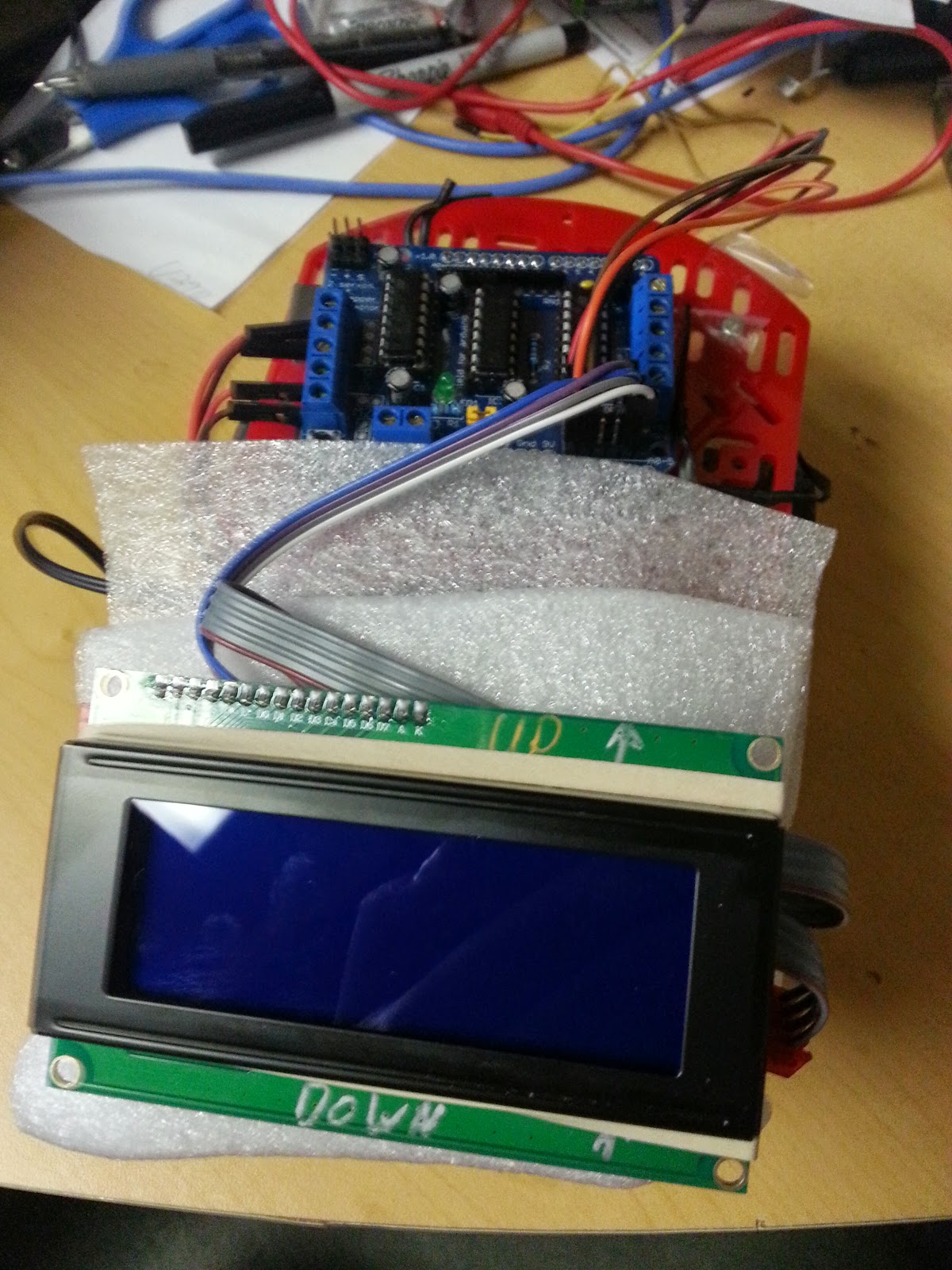
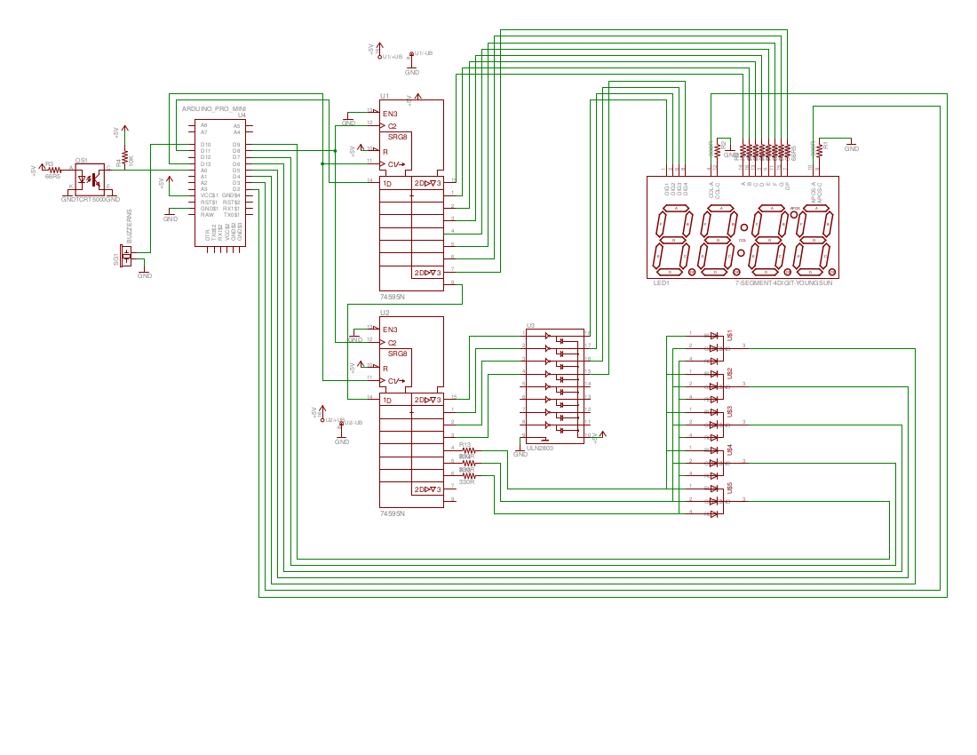
On the receiving side I got it to receive data, separate the different sensors and show a csv or human readable output on the serial port.
Receiver
My current issue is current and presentation.
The remote sensor is taking to much power for to long, considering changing so it only sends the data once and only if status is ok. If that transmission is lost we get it next round.

On the receiving side I'm wondering how to best present the info (besides serial output). The csv output is pretty simple
#Unitno,unitId,msgCnt,vcc mV,batt mV,stat,temp c,humid %
0,13C76FE0,11,4693,4092,0,22.60,42.60
1,2585C230,63,5051,2152,0,21.00,43.30
1,2585C230,65,5096,2076,0,21.00,43.30
0,13C76FE0,12,4693,4092,0,22.60,42.40
No time since then I would need a rtc somewhere and the time is when it's coming so the receiving app can time stamp itself.
I could add a 4x20 lcd but with more than 4 sensors it gets hard to present anything useful.
Thinking of sending it to an raspberry pi where I add it to a database and then have a website that can do the presentation.

One more thing to figure out is distance, how far away can a sensor be and what can be done to increase the range.


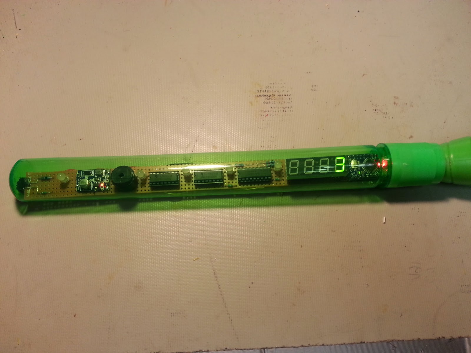
Update1: Managed to put it all inside the box
But I think I may have to find another sensor/add 1 battery, the stepup- converter is killing my battery even when idle.


Update2:
Done some testing and decided that the stepup converter must go. Running it on 5V means higher current to start with and the converter does use some power also. I have removed the power LED in the arduino so now it's only on when sending. I also improved the sleep part so it's doing a full power down and let the watchdog start it up every 8 seconds, so time between transmissions need to be a multiple of 8sec.
Some numbers measured with a cheap multimeter.
The battery lifetime is based on 2400mAh batteries, a sampling of about 4 sec (have to check on why so long) and with a rest of 72sec:

Running on 5v from booster, mA after booster:

Active: 15-18ma
Rest: 0.58mA
Batterylife: N/A (70 days - but not really relevant since that's after booster)

mA before boster:

Active: 42-44mA
Rest: 1.49mA
Batterylife: 27 days

Power usage during using 3xAA and no step-up

Active, 3-4 sec, 11mA
Resting - 78sec, .46-.47 mA
Batterylife: 98 days

So if I run on 2 batteries it takes 3x more power during rest than if I run on 3 batteries and no booster (partly because it's then running on 3.6v instead of 5v) and that means 3.6 times longer between battery replacements. While the arduino can run of 2 batteries the sensor requires at least 3.3V so I need 3x.


Version - 0.4 of the remote sensor code, still need a lot of cleanup but it works


2014-09-12

Clock system


It's a clock challange open to make the ultimate clock that I joined (please go there and vote). Since it been a while I feel it's time to write down something about what I'm up to in regards to it.
I looked around a lot trying to figure out some new way to present the time but it's not that easy. I was thinking on things like a bookshelf, Domino 9, gear clockrolling ballPropeller clock and many many more but whatever I thought about it was already done a thousand times.
I talked to a friend for ideas and he suggested to attack the backend instead. The plan is to make a clock that is modularized. It has a base with the smarts in it. Then you plug in a presentation module on top to show the time. In the base you have holes/slots where you can plug in modules for atomic clock, GPS time, ntp over wifi (both receiving and broadcasting), your smartphone, radio, audio and so on.
The units communicate over i2c/spi bus with some defined protocol so that you can plug in things and it just discovers it and starts using it.
Now the first version will be some 3D printed base with modules that plug together. For display it can be a simple 7SEG display or analog clock that is just put on top.

2014-07-17

Light following robot

I joined the Ottawa Hacker Challange where you get a mystery sensor and this time it was a light sensor that need to be used.
For some time I wanted to make a simple robot and after watching lots of line following robots I now decided to make a light following robot.
I got a basic chassis

and the plan is to put two servos on top with the light sensor on. They then sweep around, find the brightest direction and go towards the light. With that I can have a light source hanging in front of it and it will follow it, at least that's the plan.
I added some hardware to read the encoder wheels


 to be able to control the direction and a I2C based LCD to show some numbers.


Got it to partly work but the motors are so weak and unbalanced that when I go full speed on one and 60% on the other it still can't go straight and when I go below 60% it stops completely.
While pondering  on what to do I passed by a thrift store and found a simple radio controlled hummer that I bought for $10.


The default function is binary, it's full speed forward or back and full tilt left or right so it's limited but I'm not interested in that part, I did go for the chassis. A single motor that I can control the speed on, replace the full tilt servo with one I can control with better precision. Add the sensors and so on and I have something that might work.
So far I only managed to rip out the provided electronics and put in my servo but I'm not sure if it's strong enough.


Update1:
Added the controller and got it to move around. It is moving a little at 25% and is to fast at 100%.
Steering works but is somewhat limited, no more then 20 degrees left and right (=total of 40) but it was like that before I changed it so it's not my mod that caused it.

What's left now is to figure out how to mount all parts and some programming. May need to add some kind of remote control to stop/start it or it will drive around at some predefined speed all the time.


2014-07-08

Kinetic Lance - completed version

Now when it's completed I do a new follow up on my previous post on how what to make with a proximity sensor.


A friend (who like to stay off the net) suggested a kinetic knife. It's about a knife that has to come close but it can't touch. (The idea comes from the books/movies "Dune" where they have kinetic shields).


After working on it for a while I have now managed to get everything together and working. Did some minor changes but over all it works better than expected.

From the top - component list
* Lance from the $$ store
* Long breadboard
* 2xAAA battery holder (inside the handle)
* on/off switch
* DC-DC Booster to convert 2.4V to 5V
* Arduino Pro 5V 328 16MHz
* 2x74HC595 shift register
* 1xULN2803 driver
* 5 RGB LEDs
* 4x7SEG display, Common Cathod
* Buzzer to make some noise
* 9x66.5 ohm resistors (58-100 probably works fine)
* 1x10K ohm resistor
* 5x330ohm resistor
* tcrt5000 sensor
* some wires


The Schematic for it, the battery and dc-dc is missing and using common anode RGB LEDs could been better (use driver IC instead of shift register) but now i had common cathode ones at home so that's what I used:
After figuring out where to put everything and solder all the wires the assembly was done.
The programming was next step and after changing around things I managed to get it to work the way I want it - here is a short demo


The code contains interrupt timer controlled driver for the digits using SPI to send it to the shift registers, just load an array with the numbers you want to display and forget about it. I'm happy with the way that part of the code worked out and will probably use it else were if I need it some other time.
The rest is just some logic to count points and make the RGB LEDs flash.


Version - 0.5 of the code

(photo credit to my shy friend)